
Selection of 5 key parameters for Chip Burn in Test Fixtures
Engineers performing chip aging tests know one thing: No matter how well designed the burn-in board is or how precise the temperature control is, a malfunctioning aging test fixture ruins the entire experiment.
Intermittent contact problems, probe shrinkage at high temperatures, and chip cracking from cap deformation are common in mass production aging. Most issues aren’t fixture quality problems, but rather result from overlooking key parameters or falling into cognitive traps.
This article skips theory and goes straight to practical advice: Which parameters matter when choosing a chip aging test fixture? What pitfalls trap beginners? How can you avoid them?
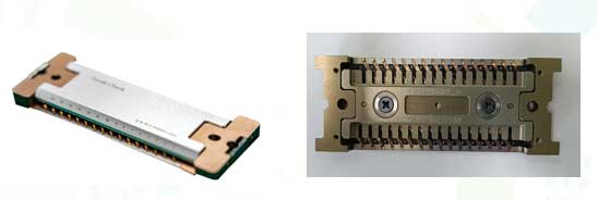
Five Key Selection Parameters You Can’t Avoid
Whether you test automotive, consumer, or industrial-grade chips, these five parameters must be checked.
Contact Resistance and its High-Temperature Drift
Many datasheets show ‘contact resistance <50mΩ,’ meaning new probes at room temperature. Aging tests run for hundreds of hours at 125°C or 150°C, increasing contact resistance from oxidation, plating wear, and probe fatigue.
Ask suppliers for contact resistance curves after high-temperature aging (125°C, 1000 hours). The drift should not exceed 20% of the initial value.
Don’t rely on initial data or continuity at room temperature. Verify by aging the fixture in an oven, then measuring contact resistance.
Probe Rated Current and Temperature Rise
This is often overlooked. Power pins or chips may need 2A, 3A, or 5A per pin. Applying high current to standard probes (rated 1A) causes increased resistance, voltage drop, or probe overheating and melting, which can damage circuit boards.
Tell suppliers the maximum current per pin. Use standard probes for signals, and high-current probes for power pins.
Don’t guess if probes are suitable. Test temperature rise: apply rated current, use a thermocouple nearby. If the temperature rises over 30°C, choose a new probe.
Long-term thermal stability of the insulating material
This is the most problematic part. Many inexpensive fixtures use ordinary plastic, which softens and deforms after a few weeks at 125°C. This leads to changes in pressure, unstable contact, and probe detachment.
Confirm insulating material is PEI, PEEK, or high-performance LCP. Ask for HDT and RTI values. PEI handles temperatures over 170°C.
Don’t accept vague claims like “high-temperature resistant plastic.” Ask for material grade, e.g., “PEI 1000 or PEI 2300?” Exclude suppliers without datasheets.
Probe Lifespan (Molding and Removal Cycles)
During mass production, chips are repeatedly replaced, and probes undergo many compressions and rebounds. Towards the end of their lifespan, elasticity drops, plating wears off, and contact failures rise.
Get molding and removal lifespan at rated stroke and room temperature from reputable suppliers. For high-temperature aging, ask for accelerated lifespan data.
Don’t trust marketing figures blindly. Clarify test conditions: stroke, speed, resistance and failure threshold. Record and monitor the initial yield, and replace the fixture if it drops.
Downforce and Chip Package Tolerance
Each package has a maximum permissible downforce. For thin QFN packages, downforce over 20N may crack the chip or damage solder joints. Chip burn in test fixtures often need more downforce to ensure reliable contact.
Get the pin contact force and total downforce from the supplier. Compare with the package datasheet limits and allow a safety margin.
Don’t ask only if it can be pressed tightly. Get actual downforce values. If total downforce exceeds package limits, request low-bounce probes or floating pressure caps.
Conclusion
A chip aging & burn-in test fixtures may seem minor, but a wrong choice can destroy a testing project. Remember: A good burn-in socket isn’t the most expensive or cheapest. Choose the supplier who, after clear requirements, gives clear data and assumes clear responsibility.